Industrial Design from Zero to Product
People often ask us how we made the Aeroscope wireless oscilloscope probe with just two electrical engineers on such a complex project. It encompassed not only sophisticated analog electronics, but also FPGA, firmware, software, mechanicals, and industrial design. We essentially just dove right in, voraciously working on any available task. I took the reins on the mechanical aspects of Aeroscope, including the industrial design.
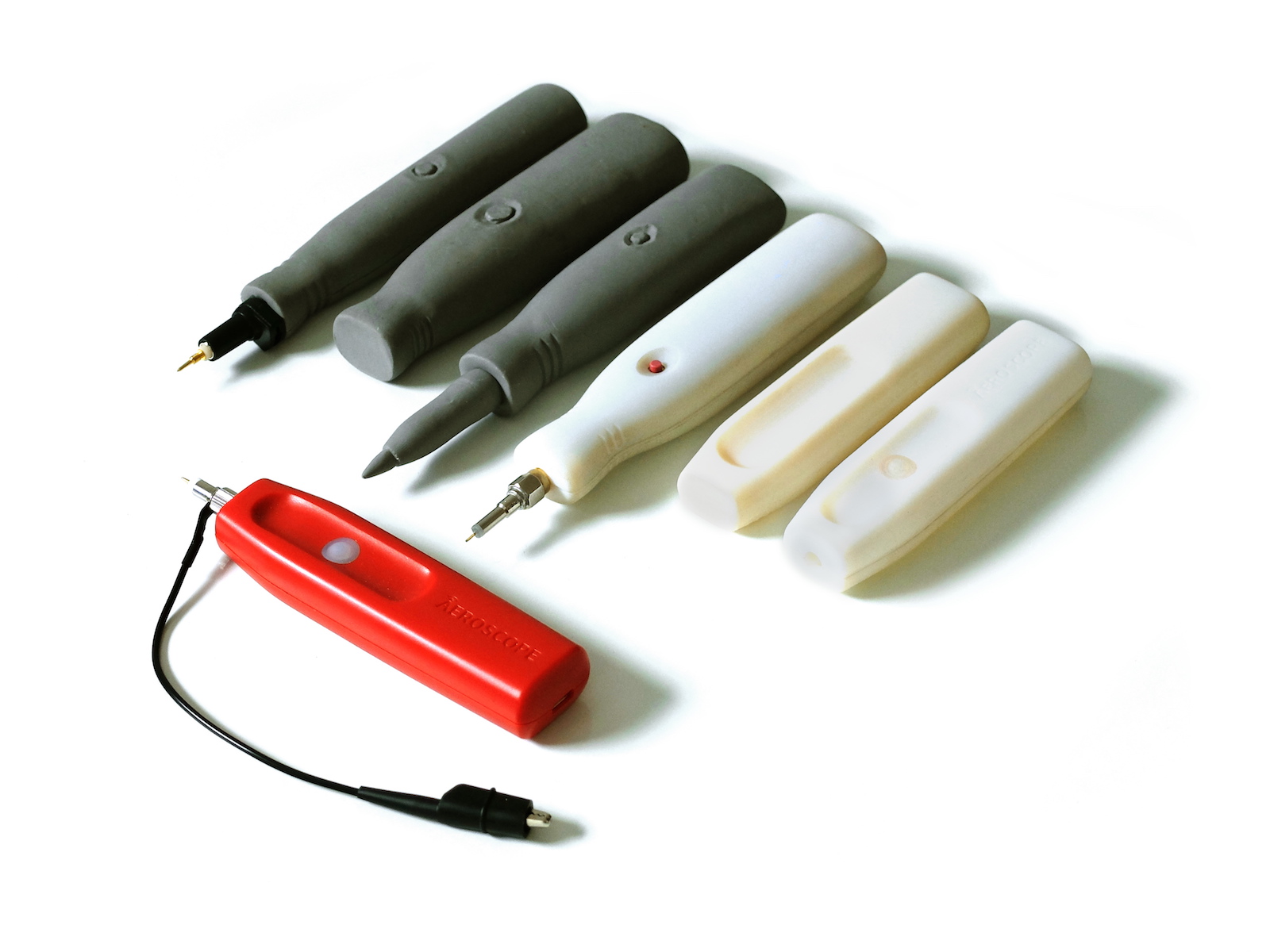
One thing I learned throughout the industrial design process is the importance of iteration. Just like in engineering, it is rare to stumble on the best solution right away. The beauty of design is that you can iterate much faster than hardware or even software. Since this was literally my first rodeo, my main weakness was thinking too much like a hardware engineer. I was overly concerned about cost and space for the printed circuit board and didn’t think enough “outside the box.” As an EE, I had never really done any non-engineering design work. My main exposure to it was by working at several consumer product companies. From my limited experience, I knew that to make this product work it not only had to look good, it had to be easy to use as well. On top of that, we had to be able to produce it with our meager budget. To get the right combo of looks, ergonomics, and manufacturability, I wanted to try out many designs ideas very quickly and settle on one with the optimum mix. Since a scope probe is something you hold in your hand and interact with, jumping straight into CAD seemed like a bad idea. I had to be able to feel it, so I chose clay as my prototyping medium. Specifically, I used Sculpey modeling clay because it was easy to work with and test ideas. When I was finished with playing with an idea, I could just bake it in the oven to harden it and make it durable enough to handle.
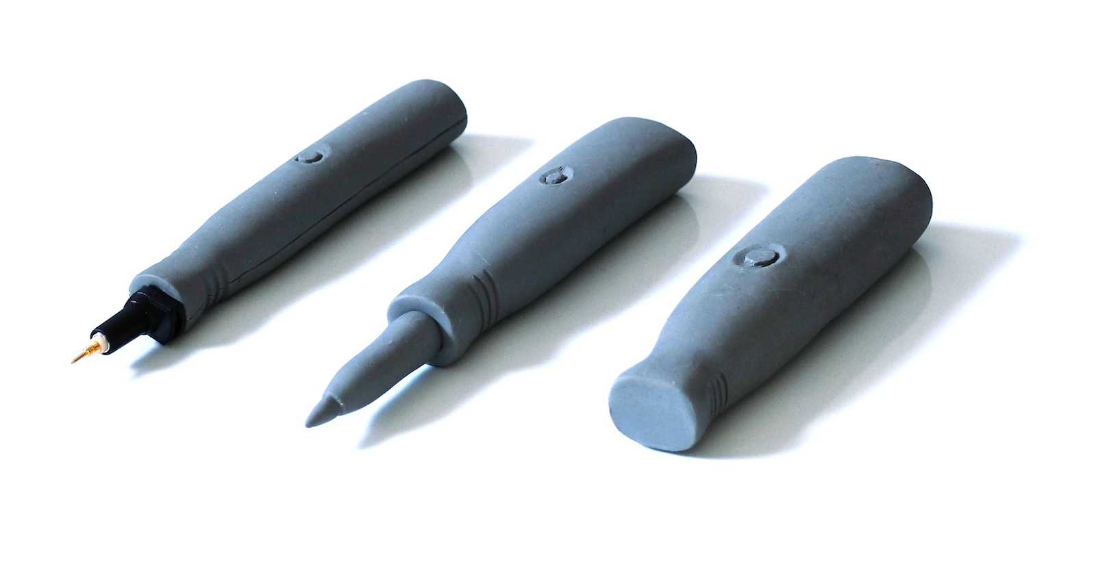
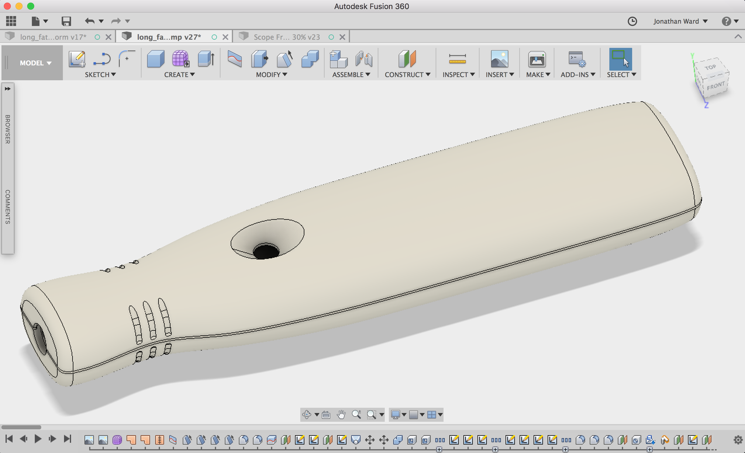
My first idea was just a simple pen shape, modeled in clay. This left very little space for any internals, though. My engineering hat took over — again, my main weakness in this process — and I added extra internal volume for the next few iterations, sacrificing ergonomics. At this stage, I felt confident enough to try to CAD up some of the ideas. I used Autodesk Fusion 360 CAD software to make a 3D computer model of the best clay prototype. The sculpt tool of Fusion 360 really helped out here. Many CAD packages require you to model complex organic forms from 2D sketches in a tedious process similar to building an old wooden sailing ship. This can work well, but you get into trouble when you want to add features not present in your reference design. Fusion 360 includes a feature that essentially allows you to digitally sculpt a virtual block of clay. This really helped when I wanted to tweak certain elements that weren’t in my clay model. I started by importing a top view and a side view of the clay model and tweaking the virtual clay to match.
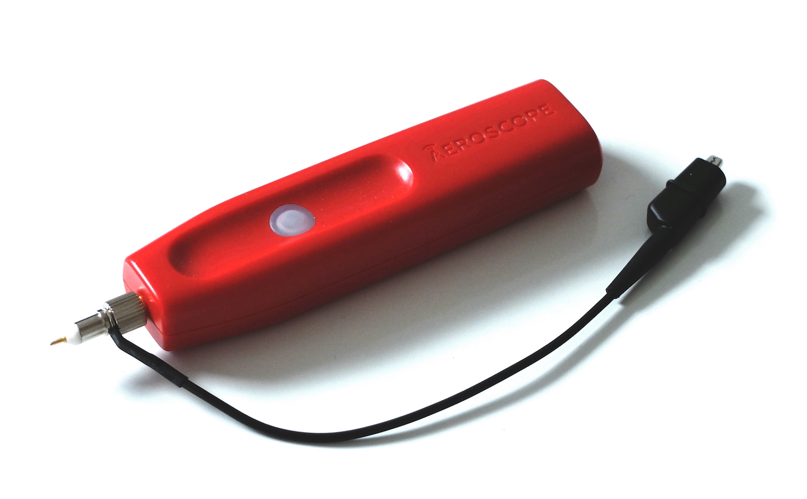
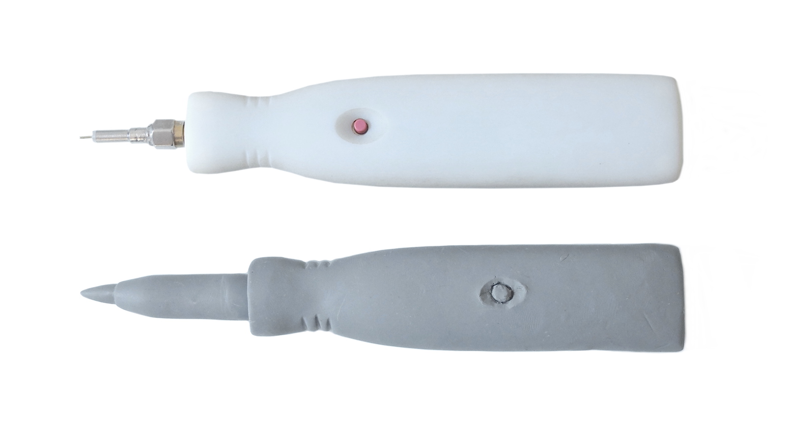
Once I had a 3D model, I ordered 3D prints from a San Francisco company called Fictiv. I was shocked when the prints showed up at my apartment (I was living in San Francisco at the time) the next day and delivered by bicycle! They were also much higher quality that we could have achieved with a hobby printer. We used this 3D printed case together with our first form factor PCB to make the first working prototype.
Giddy from the excitement of the first form factor prototype, I thought the industrial design was done. That is, until I started showing it around. Everybody was very positive, but the overwhelming feedback was that it was too bulky and awkward. I’m glad I had their feedback because they were definitely right. Back to the drawing board, I thought up some iterations of the design and decided it would be easier to take the existing CAD model and make tweaks rather than start all over from the clay stage. Here is where Fictiv really pulled through for us. I was able to tweak the CAD to make a few different options and get prints back the next day like before. This time, however, I continued to make adjustments based on the 3D prints. The short turn-around was critical at this point. I was able to do multiple complete design cycles inside of a week.
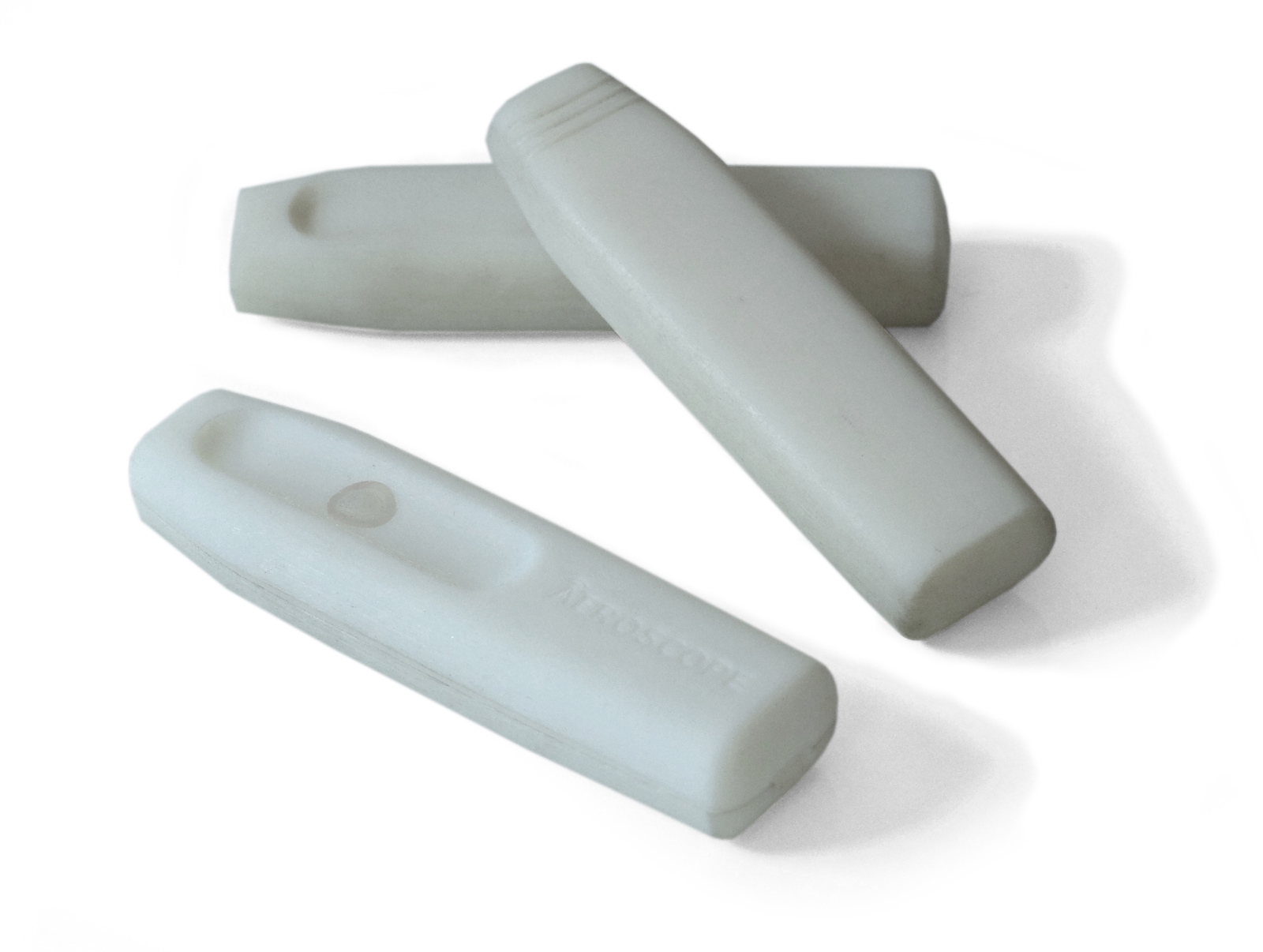
After a few of these “CAD tweak, 3D print, repeat” cycles, we settled on a final shape. It was much smaller, better looking, and more ergonomic than anything we had previously. The next step was mechanical engineering to turn the industrial design concept into a full mechanical design that could be made out of injection molded plastic. But that is another story…