Jonathan Ward
During my Spring semester of 2006, I took a graduate-level biomedical engineering class entitled "Electronics for BMEs." Because it was a graduate class, I had to complete a semester project.
 Based on some suggestions from the professor, my partner Steve Majerus and I decided
to make an ultra wideband EKG transmitter and receiver for our project.
I had been fascinated by radio communication and thought that this would be
a good opportunity to get my hands dirty.
When we came up with the idea for the project, we thought that most of hard work would be done by radio ICs. Intel and Freescale had websites touting their ultra wideband platforms. The main part of the project would be making a system to enable these ICs. We even placed an order for samples from Freescale, but they never came. It took us a week or two to realize that these ultra band ICs were vaporware.
By this point it was too late to change projects. Furthermore, I didn't actually want to change. Ultra wideband was very interesting. From my research, I gained the confidence that I could create a working system. Faced with the daunting prospect of creating a radio system from scratch, we pressed on.
The best information we found came in the form of IEEE journal articles and old patents. The modern information was concentrated mainly in short technology overviews in trade publications. There was no substance. Ultra wideband was a largely neglected field, but every decade itseemed, there would be a resurgence of interest.
Modern day patents seem very obfuscatory in nature. The goal is to get maximum protection while revealing the minimum amount of technical details. In contrast, older patents seem to genuinely want to teach the reader how to realize the technology. It was from these outdated patents and journal articles that we got the inspiration for our work.
 The real enabler of this project was my friend Eddie Burwell who had a collection
of old "obsolete" test and measurement equipment. We were lucky that he
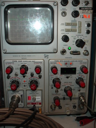
owned a Tek 564B analog sampling scope. This oscilloscope had several
GHz of bandwidth and was just what we needed to develop our system. His
expertise in electronics also helped us out immensely when we ran into
problems.
An analog sampling scope is an interesting beast. It only takes one sample per incoming trigger. Because of this, it can only be used to measure repetitive waveforms. It builds up a waveform one sample at a time by changing the sample point picoseconds at a time with respect to the trigger. It uses some very high performance "obsolete" parts that are no longer in vogue and thus no longer produced. There are modern techniques to obtain this kind of bandwidth, but analog sampling scopes still have some capabilities that the modern equivalents lack.
After much experimentation, we were able to create a system to transmit and receive ultra wideband pulses. In order to use this to send data, we settled for on-off keying because it was very simple and would allow us to actually finish our project within the semester. True ultra wideband systems use other modulation schemes such as pulse position modulation. These require precise timing circuits, however and would take longer than our timeframe allowed.
In operation, when sending a "1," the transmitter would continuously send pulses to the receiver. Likewise, when sending a "0," the transmitter would transmit nothing.
We used two Atmel AVR Mega8s for the transmitter and receiver. Instead of rolling our own data encapsulation scheme, we decided to use the UART ports of these devices to take advantage of the asynchronous and parity features.
 To detect the ultra wideband pulses, we chose a high bandwidth log detector that
was capable of accurately measuring signals with a high peak to average ratio.
We discovered an error on the detector's datasheet that prevented it from working.
Even when we corrected the problem, its performance was pretty bad. We actually got
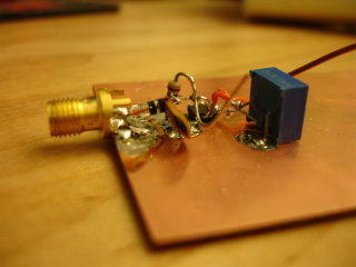
better performance from a home-made diode detector that we cobbled together.
The project was very cool because I got my first taste of RF and was exposed to a whole new domain.
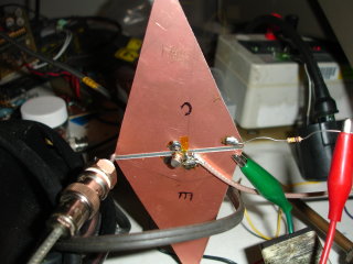
These videos shows our ultra wideband transmitter sending pulses to Eddie's Tek 564B through the receiver antenna. This test setup was complicated because it was hard to get the oscilloscope to trigger on the pulse. We finally managed a workable solution by running a short (6 ft) piece of coax from the scope's trigger input to the transmitter. The receiver antenna was connected to 20 ft of coax coiled on the bench and then to the scope's input. With this setup, the trigger wire would pick up the radiated pulse from the transmitter and cause the scope to trigger. The pulse would be received by the receiver antenna and then travel through the long coax cable to be displayed on screen. The coax was necessary because in order to see the whole pulse, we needed to delay the incoming signal with respect to the trigger.
The videos show how changing the orientation of the receive antenna and its separation from the transmitter changes the received waveform. The transmitter is only sending out one pulse, but reflections from the room cause additonal pulses to appear at the receiver. The ease with which these reflections appear inspire me to one day create a personal radar system.
Rotating the antenna upside down changes the polarity of the incoming pulse. Similarly, moving it back and forth changes the path delay of the pulse. Do you see how you can use this system to measure the speed of light? The oscilloscope displays 1 ns per division in these videos. By moving the antenna a precise amount and looking at the change on screen, the speed of the signal (the speed of light) through air can easily be measured. We confirmed that light travels about one foot per nanosecond.